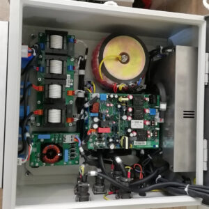
AMVAJE ABI FCV CONTROL
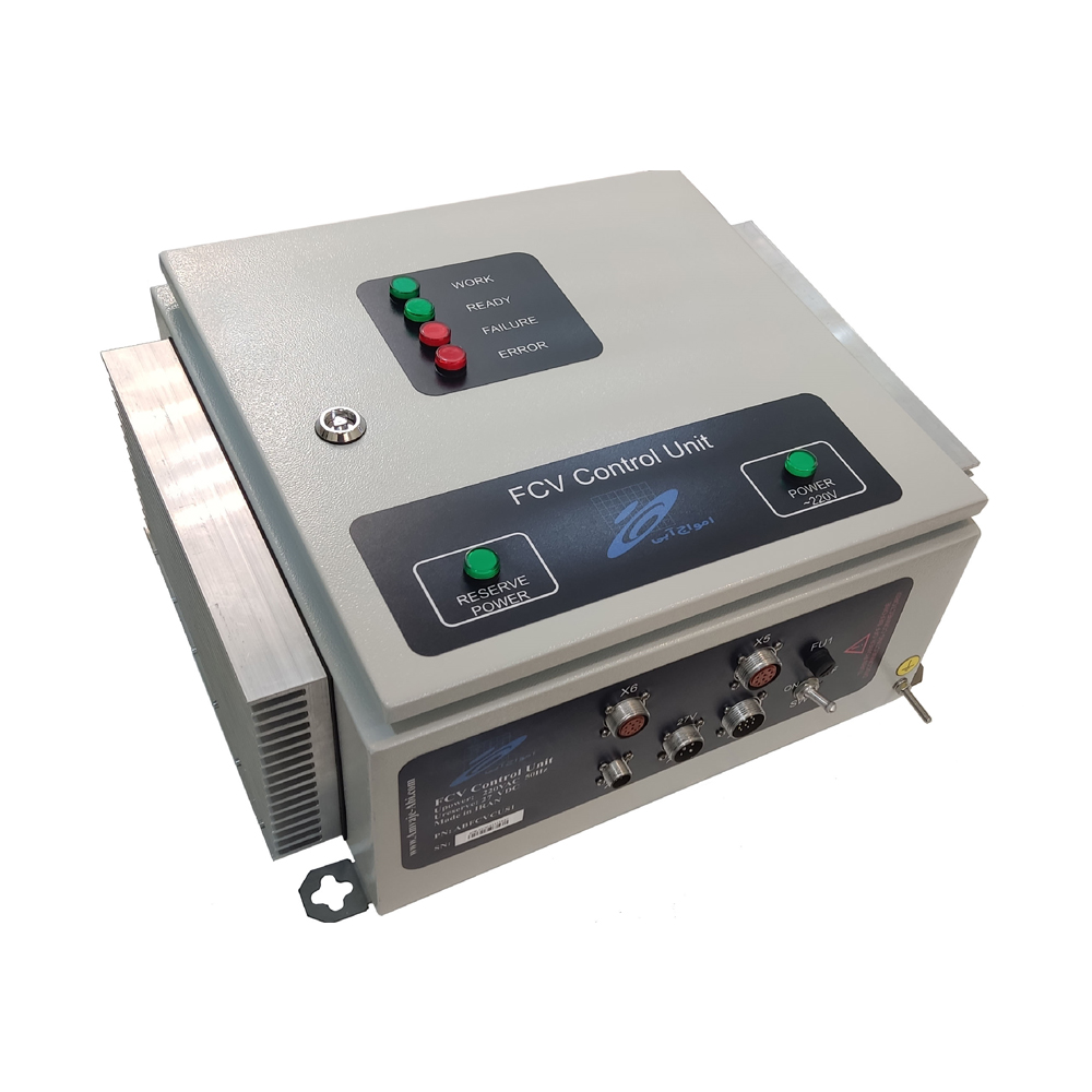
- The FCV (Fuel Control Valve) Control Unit regulates fuel input to the turbine via a turbine fuel valve.
- Maintaining high-speed and responsive turbine fuel input is crucial for gas turbine speed control.
- FCVs primarily use stepper motors due to their required sensitivity and high speed.
- Applicable in Turbo-compressor speed control, Turbo-generator speed control, Control of Combined Cycle Gas Turbines (GTCC), Burner and Boiler fuel control
Cards and related modules
Quality Assurance for Products
Product Authenticity Guarantee
Shipping Everywhere
Responsive support
General Information AMVAJE ABI FCV CONTROL
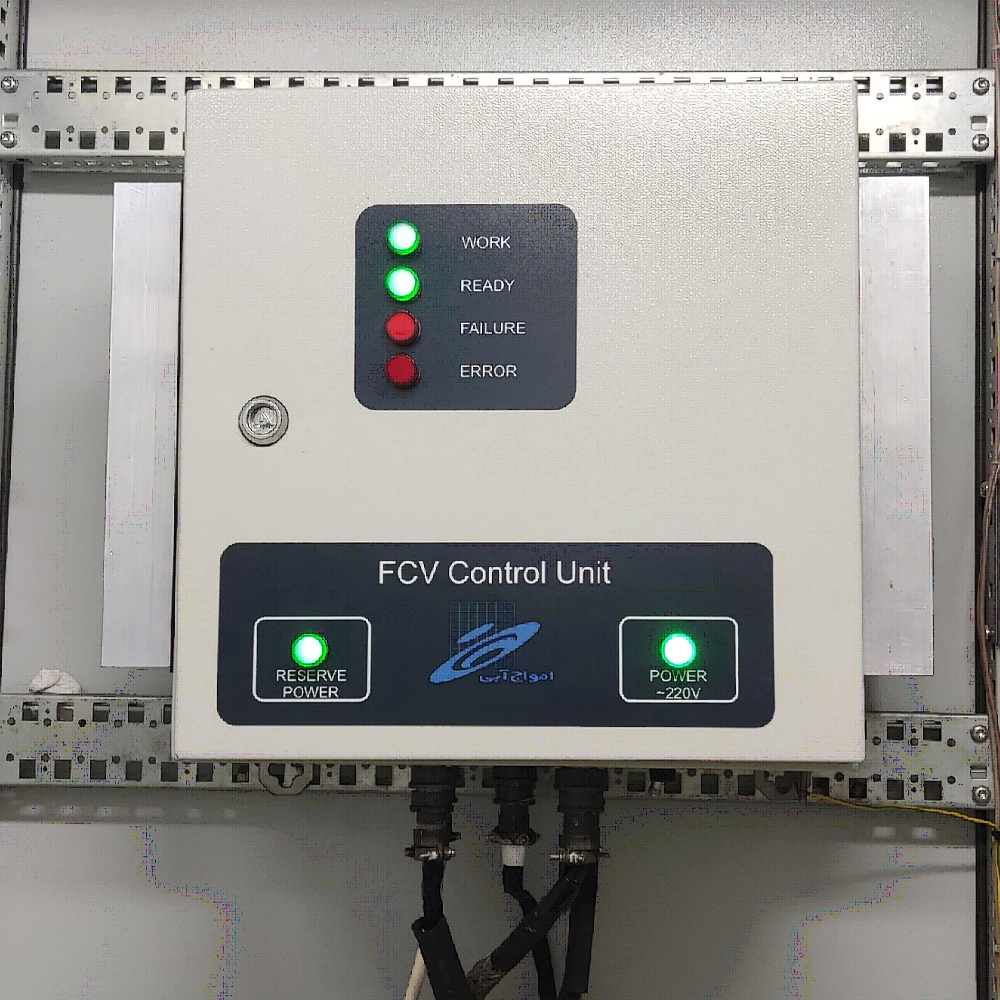
FCV Control Unit
The FCV(Fuel Control Valve) Control Unit is a turbine fuel valve controller responsible for regulating the fuel input to the turbine. Given that the speed of gas turbines is controlled through turbine fuel regulation, the process of controlling turbine fuel input with high speed and response time is crucial. This is particularly important in cases where turbine speed control has higher sensitivity, such as gas turbine generators operating in synchronous mode with the grid (e.g., Gas Turbine Generators in scenarios where the generator output is synchronized with the grid). Therefore, the functional sensitivity, response speed, accuracy, and resolution of the FCV significantly impact the proper functioning of the turbine.
Due to the required sensitivity and high speed, FCVs are primarily designed and manufactured using Stepper Motors. In some advanced FCVs, two stepper motors with differential performance are occasionally used to adjust the valve’s open or closed position.
Applications:
- Control of Turbo-compressor speed
- Control of Turbo-generator speed
- Control of Combined Cycle Gas Turbines (GTCC)
- Control of Burner and Boiler fuel
SUDT-8, an enhanced and improved model of the FCV system:
- Rectification of PCB issues leading to burning incidents.
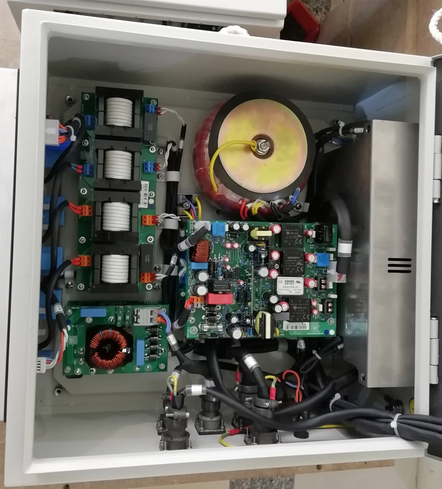
- Reduce wiring in the system by employing spacers instead of wiring to connect the Receiver and switching boards.
- The VDR was placed on the PCB instead of in an external placement.
- Revision of the arrangement of internal boards and reduction of wiring paths.
- Reduction in the number of system boards, including:
- Integration of Power 220 and Rectifier boards into a single board.
- Integration of Micro and LED boards into a single board.
- Replacement of more suitable and up-to-date components, including:
- Substituting the ATtiny13 microcontroller on DC/DC and switching boards with an ARM STM32F030 microcontroller, featuring improved quality and programming from scratch.
- Replacement of the micro on Power 220 and Power 24 Control boards with a comparator circuit while preserving the possibility of using a microcontroller.
- Substitution of Switching circuits supplying power to the microcontroller board on the Switching board with reliable DC/DC modules.
For more information on this product, please refer to the product catalog.

